
Vodkaman
-
Posts
7,434 -
Joined
-
Last visited
-
Days Won
238
Content Type
Profiles
Articles
TU Classifieds
Glossary
Website Links
Forums
Gallery
Store
Everything posted by Vodkaman
-
Let me add that this stuff is not intuitive, it is not obvious or easy. If anyone who has been sent the tools is not grasping the idea, PLEASE contact me by PM or post here for public viewing, and allow me to help you understand how it works. I am good at the technology but not so good at the interaction. Please allow me to redeem myself Dave
-
Sent. Dave
-
It is one of those strange things that has been around for all time. We have all experienced it at some time. Everyone who has ever picked up a table tennis paddle has seen the effect when they toss the paddle up in the air, watched it flip over and then caught it again. So well was the movement known that science forgot to look at it and come up with an explanation. Dave
-
Travis - my hard-bait molds should fare better being a cold process with a little exothermic reaction. It will be interesting to see if my suggestions can extract more pours directly from a 3D printed mold, it is just a prototyping method, and may produce enough for own use only applications. I do agree that printing a positive and molding in POP or other material would be the way to go, as I posted in my first reply. Dave
-
Good reply Anglinarcher. My prey are bawal, a deep bodied very aggressive fish, which explains why I only need a belly hook. Dave
-
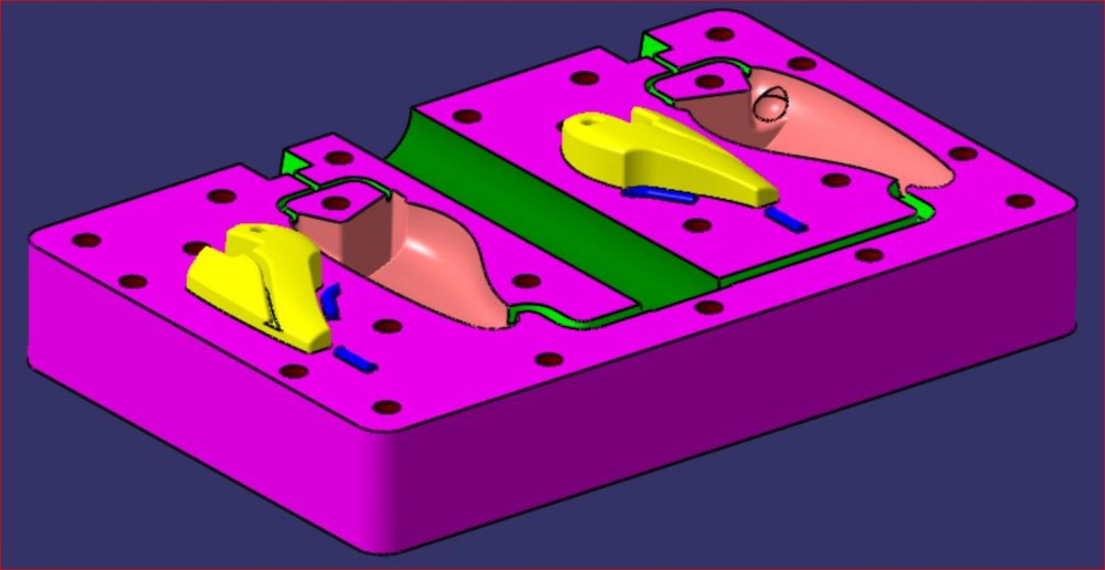
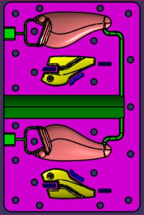
Mark - Yes, basically what I want them to do; between plywood backing plates, but with a lot more clamping. I didn't mention plywood thickness, I would say at least 0.5" or thicker. The problem with a 3D print the size of a mold is that it can take 24 hours to print, and so the overall mold thickness tends to get compromised. BUT, the mold is going to warp what ever thickness that you make it except it is going to require more effort to correct an overly thick mold, and it will take more intermediate bolt clamps to correct an overly thin mold. As always, design is a compromise. Just a thought - If we ever get the PLA molds to work, we could consider internal cooling pipe matrix for an air flow or possibly a water flow, but we should solve the immediate problems first. Here is an ISO view of my hard-bait mold half. Dave
-
Well, I am not a regular fisher, so I will bow to general opinion. But, I do have a lot of success with the belly hook on my tests. Dave
-
I mainly build small lures 2.5" or less. I use the belly hook and delete the tail hook as unnecessary. The belly hook should be far enough back so that it does not foul the lip or the line. The hook dangles roughly in line with the rear of the body. Nothing wrong with a single hook, just more chance of a miss. Dave
-
CNC is a BIG step, so good luck with that one. The problem is that the mould plastic softens with the heat. With the standard 4-corner clamping, the mold will still bow in the center, even clamp plates may not solve this. Clamping needs to be close to the cavities and well distributed. Here is a pic of the mold I was about to have printed, but I have since changed the design in my head, and so needs remodeling. You can see all the clamp bolt holes. As a side note, you can also see that this plate is the same for both halves; flip and rotate 180 degrees. Dave
-
Try building more clamping holes into the mould, back drill through some plywood backing plates and clamp up the sandwich tight. This is obviously not a convenient solution involving more work in putting the mould halves together, but it may get you more pours or even solve the problem. If you try it then give me feedback, positive or negative. Dave
-
Unfortunately, the PLA melting point is roughly the same temperature that you are pouring, and so severe distortion is unavoidable. You need to find a printing material with a higher temperature tolerance. Distortion can be mitigated by load spreading plates and plenty of clamping. But you still have the problem of pouring into an insulating material with poor cooling qualities. I don't own a printer but class myself as a CAD expert seeing as CAD design has been my job for 35 years. Also, I am hard-baits and so not hampered by the extreme temperatures of the soft-bait pourer. The best that you can do IMO, is print a master and then cast it in POP or some other casting material that can take the heat. As far as hard-baits is concerned, my plan was to print a PLA negative mold to cast a positive mold in another material, designing the PLA negative such that the resulting positive was symmetrical, in other words, both mold halves were identical, so only one PLA master was needed. Unfortunately, the heat distortion from the exothermic reaction of POP or other cast materials made mating the halves impossible. With my financials being stretched and 3D prints costing $100 a time, I cannot throw money at a whim. However, I have a lure design on the go that needs building, and the replication accuracy required means that only 3D printing can give me what I want. I will have to design a positive and print both halves for pouring polyester resin. The design will have a ridiculous number of clamping holes and load spreading wooden plates. The design will help me to determine the minimum clamping required as I try various clamp configurations. I am trying to summon up the enthusiasm to hit the design again as lure wall thickness was a problem on my last attempt, giving incomplete pours. I really do need my own printer as this project is costing me way too much in 3rd party services. I know it makes fiscal sense, but I want to see some success before I commit. The beauty is that if the design is successful, I could take it straight to production injection molding on a grand scale with confidence. Good luck with your project. Dave
-
I do try Mark, but I find it difficult to explain. I always end up writing a novel Dave
-
As I do not build gliders or jerk baits, all that I can do is throw a lot of theory out there, to help you understand how the lure works. Understanding the theory helps the builder to design a lure to take advantage of the forces accordingly. Of course, experienced glider builders will have already figured this stuff out even if they do not know the reasons why their lures work. Experience is a valuable tool, theory only gives you a ‘leg up’ at the start. As you have already figured out, this is a very complex issue with multiple factors to be taken in to consideration. The apparent ideal solution for a lure to swim a long distance with efficiency is an arrow with all the weight at the front. But we already know that this would not work in water as it does in air because of the nose down attitude, like I said; multiple factors. Also, the super aerodynamic shape of an arrow is designed NOT to produce vortices. When we fire an arrow in air for maximum distance, we apply great force and we aim up at 45°, and due to air resistance, the arrow falls at 70°+. Target sports for darts and archery only use the top of the flight arc. Also the arrow is designed not to swing from side to side, a definite requirement of the lure. As for the lure; we want it to travel in a straight line as far as possible, then on the next pull, we want the same again only in a different/opposite direction (left/right). So, what causes this desired change of direction? The answer is vortices, my favourite subject. A waggling lipped lure generates a rapid series of vortices that cause the lure to waggle left and right. The sharp lip causes vortices to be created at a relatively low speed, and the theory of the ‘Kármán vortex street’ causes the vortices to rapidly alternate left/right. But still, the lipped lure requires a minimum speed to operate. The lipless glider still creates vortices but has a much higher minimum speed to create the vortex. The operation of the lure is to tug or jerk the lure. A single vortex is created and no more as the lure is already slowed below the vortex threshold. This swirling vortex sucks on the rear half of the lure body causing it to change direction. The next jerk causes the vortex to form across the back of the lure and sucks it in the opposite direction. As the lure slows down, that single vortex is still there, working on the lure, sucking it further around. This effect can be seen on multiple section swim-baits; a steady, constant retrieve causes alternating vortices that act on the rear of the lure causing that beautiful snake action. BUT, if you jerk the jointed swim-bait, the lure curls around even 90° and beyond. Check out the video, you can almost see the vortex sucking the lure around in the jerk sections with a little imagination. The above is the basic mechanics of what is going on. Now we have to figure out how to use the mechanics, the theory, to make the glider lure swim how we want. To start with, I use an analogy that I have talked about many times; Grab a 2 feet length of dowel in the middle in your fist. Rotate your wrist rapidly left and right. The dowel swings fairly easily. Now add ¼ pound of lead at each end of the dowel and repeat. The dowel is much more difficult to swing left and right. Now put the two weights at the center of the dowel and repeat. Once again, the dowel swings easily. This is the effect of inertia. We want the glider to change direction but we want to resist the continuing change of direction. The solution is to increase resistance to direction change by increasing inertia. By placing weight at the front and rear we increase inertia and resist the change of direction. But as always, design is a compromise. If the inertia of the lure is too great then the change of direction will be minimal or even nonexistent. You may end up with a straight swimming torpedo. Another feature is the depth of the lure body that the suction of the vortex acts upon. You may think that a deeper body with a larger surface area would resist the side movement, this would be incorrect at least according to theory; the suction force of the vortex acts on the side surface area of the lure, reduce the area and reduce the force. But yet again, design is a compromise. If you reduce your lure to a torpedo cylinder, no vortex will be created in the first place. If your lure swings excessively as it slows down then consider reducing the body depth. The reduced depth will also reduce resistance to forward motion. Once the glide motion clears the vortex, it will travel aerodynamically like a torpedo. We only require the vortex sucking effect at the initial tug of the lure, if the glider can swim clear of the vortex then it will continue in a straight line for more distance. If the glide distance is short and the lure continues to turn; reduce body depth and/or extend the weights to front and rear. If the lure does not change direction then no vortex has been created, you have a torpedo. You can add a flat to the top of the nose to help the vortex form, or increase the depth on the next build. Gliders need to naturally float horizontal, but the rest is a compromise between body depth and ballast distribution. Dave
-
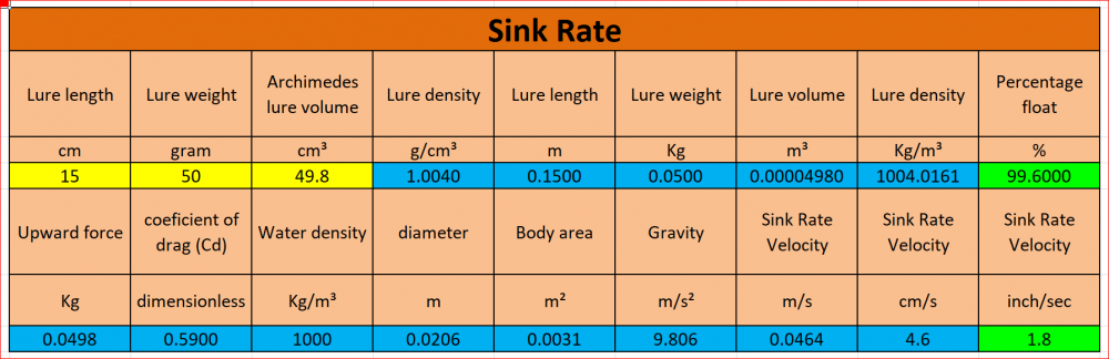
OK, I think that I have cracked the sink rate calculation. Because the plan view shape and cross sectional shape cannot be tabulated, I have used the lure volume and the lure length to calculate the dimensions of a cylindrical body and applied the sink rate formula to this compromise body. I have to say that the numbers look very good. All you have to do is enter the lure length, the lure weight and use ‘Archimedes Dunk Test’ to enter the lure volume. The green boxes show the percentage float (less than 100% = sinker) and the sink rate in inches. The tool is another spreadsheet. PM me your email address if you want to have a play. Dave
-
I am working on it, but I just cannot get the math to work. It would only be a guestimate in any case, as the falling shape of the lure (area) is a part of the equation, and the cross sectional shape. It is all about the coefficient of drag. I will work on it a while longer, but will probably have to let it go, like I did last time. Dave
-
What I should look into is sink rates. My design tools (posted yesterday) enable the builder to control the percentage of float of a lure, or even measure an existing lure's float qualities, to a high degree of accuracy. What I should do; is equate those float/sink percentages to a m/s or feet/s rate of fall. That would be impressive! Dave
-
OK, I have done a few minutes research. The conclusion is that a lure set to sink slowly, will continue to sink at the same rate regardless of depth. Something has to change either with the lure body or the water. The lure body could compress under pressure which would reduce the volume. BUT if the volume decreases then the lure will sink faster. Deep divers experience this. Near the surface the human body is buoyant, there is a net upward force. As the water pressure compresses the body, the volume is reduced eventually to the point were the body has a downward force - so we can discount compression of the lure body. The other thing that changes is temperature. The temperature is always warmest at the top and cools the deeper you go. As temperature of water increases then the density decreases. The numbers are extremely small changes from the 4th decimal place. But still, this change will set a depth for a lure, but it is way beyond our weight and volume measuring capability. The best that you can do is build a slow sinker and time it's decent. Even if you did build a lure that hovered at say 10m depth due to a temperature variation, the time that it would likely take to reach that depth would make the exercise nonsense. Sorry that I cannot bring you a more positive answer. Good question though Dave
-
I am sure that I have worked on this idea before, I seem to remember doing calculations. The problem is testing at home. I thought about clear tubing, but it was ridiculously expensive. I think at the time that I worked on this idea, my gram scale was only 1DP (decimal point) which is simply not accurate enough for the job. I will look into it and see if I can find anything. Dave
-
Density is unevenly distributed in wooden bodies. With turned bodies you have the advantage of being able to perform a floating roll test to determine the lowest point in the float and the best location for the ballast (seal body first to prevent water ingress). I am sure you will have read about this on 'Stripers' forum, but just thought that I would mention it. Dave
-
The spreadsheet that you requested (sent) will get you very close, but as for controlling the actual depth, although technically possible, the differences in water temperature from day to day will mess up that data. Also the actual make-up of the water and its minerals will make slight changes to water density. As a jerk bait, there is nothing to keep the lure down at a depth. The line resistance is always going to pull the lure up to the surface. Having never fished a jerk bait, I could be wrong on this, but all the videos I see of jerk baits, they are all on the surface or just below. Dave
-
I have spoken to Diemai over the last few days, just to say hello and ask about his TU absence. Dieter admits that his enthusiasm for lure building has waned in recent years mostly due to family issues. He still experiments with fishing equipment in his workshop as the innovator that he is, but not so much on lures. European fishing is somewhat different than USA fishing, it is more about bait fishing than lures. Dieter says ‘Hi to y’all’ and hopes, as I certainly do, that he will be back on TU sharing his knowledge and skills in the not too distant future. Dave
-
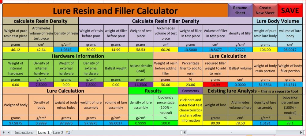
I have two new lure building spreadsheet tools available: 1 - TU resin lure calc – Designed to help with the amount of filler (MBs) and ballast required to achieve the required buoyancy without having to resort to many trial and error builds. 2 - TU wood lure calc – As above but designed for carved lures (wood, PVC or other). Many members have the Ballast Calculator, an older tool. I feel that No2 above is a better tool for this job as it takes into account internal and external hardware as well as ballast. So if anyone requests the Ballast Calculator in future, I will deliver No2 above. If anyone wants these tools, PM me with your email address and I will send both. Dave
-
My guess is that you are a member of Stripers online, if not then you should be. Both TU and Stripers will be very useful to you. No need to join just one. Dave
-
The testing of the ‘Lure Resin and Filler Calculator’ is completed. I am VERY grateful for the time, materials and effort that member ‘AndyUK’ put in on this project. Anyone who would like to test out the spreadsheet tool, simply PM me with your email address. Dave
-
Yes, welcome. Unusual for a new member's first post to have such impact (I hate the term 'newby') Dave