


Vodkaman
-
Posts
7,423 -
Joined
-
Last visited
-
Days Won
237
Content Type
Profiles
Articles
TU Classifieds
Glossary
Website Links
Forums
Gallery
Store
Everything posted by Vodkaman
-
Waiting on the fan, they are out of stock of the model I have designed for. The combined swivelling lure holder and scale mesh frame holder is almost complete and looking good. Dave
-
Great video, made me smile all the way through. Monster fish too. Dave
-
I agree with you, I hope you don't have to go through the same negative feedback that he did. You try and come up with something original and this is the thanks you get. Because of my location, I will never get to see the coverage, so I wish you good fortune and ask that you post any information you can. Video would be great, but asking a lot. Dave
-
Mark, you know I am not a pourer, but some kind of arm rest is the answer. Parker 085 mentioned the same thing. Telephone directories, or make something. I know you have a good engineering mind. You can figure this one out. Dave
-
A regular headlamp bulb is 55 Watts and at 12 Volts will use 4.5 Amperes (W = V x I). There are two of them, so the rheostat must be designed to take at least 9 Amperes plus a design consideration for heavier, higher performance bulbs plus a safety factor so that they don't blow out too often. I did a search on wiper motors and the heaviest power number I could see was 75 Watts, most motors being half this number. So your design idea of the headlamp rheostat is a good one and should work. But Mark's comments will still apply. Whether or not you could slow it down sufficiently before the motor stalls, I cannot say. Dave
-
No problem here with the hijack, the main discussion had run its course anyway. The wiper motor is a powerful motor and should be readily available as a second hand/scrap part, at a reasonable price. I cannot remember the speed of the motor, but it is still going to be way too fast and will require adjustment. The standard dimmer switch is not going to work for this motor, firstly it is too powerful for a light dimmer to handle, secondly, the dimmers are designed for 110V A/C. To control this motor would require a very heavy rheostat or some fancy electronics. Dave
-
-
A worm gear arrangement would get your rotation speeds down. 50:1 ratio would be easily achievable. Plastic gear kits should be available in model shops or try electronic component web sites, like RS components or Maplin. I know maplin have them. Dave
-
Patrick, I don't think the size of the flake is the problem. You are working with translucent colors and reflective flake. You are basically mixing light. You need to read up on 'additive color mixing', this is the theory of mixing different colored lights. The mixing of pigments produces different results and is called subtractive color mixing. The advice that you have received in the above posts is spot on and probably is the result of years of experience, you should probably at least try the ideas before you go to the shopping cart. The theory: blue + green = cyan Red + cyan = white so the red is cancelling out the cyan. Your color is not pure green, so you need to work around the red, as suggested: red, rootbeer, orange, brown. All good solid experienced based ideas. Dave
-

DIY An Instant 1/2 Rd RTV Silicone Mold For Under A Buck.
Vodkaman replied to Husky's topic in Soft Plastics
This is all good stuff Fire527. A good while back, I added a little olive oil, just to see if I could thin the RTV down a tad. It did actually set, but took longer. I did not persue it at the time, but this time I am going to experiment with glycerine. I plan on using a cake syringe. I have used these before for injecting very thick mixes of resin and micro balloons (worked well). I figure a light coating of wax inside the syringe (thanks Husky) might aid the clean-up. I feel that their is still lots to be discovered with this material. Thanks for leading the way Husky, great thread. Dave -
You can buy water slide decal paper, edit your signature on your computer and print out the decals yourself. Here is some reading: http://www.tackleunderground.com/community/topic/20029-signatures/page__p__149559__hl__decal__fromsearch__1#entry149559 http://www.tackleunderground.com/community/topic/18970-writing-on-a-crankbait/page__p__142202__hl__decal__fromsearch__1#entry142202 http://www.tackleunderground.com/community/topic/14870-stick-on-signatures-on-lures/page__p__111868__hl__decal__fromsearch__1#entry111868 Dave
-
This would work, but you would have to freeze the fish hanging vertically, in order for the that the mold will produce a symmetrical bait, otherwise the bait will be flat on one side. Doable though. Dave
-
Sorry that you are not getting the results. See if you can find any local electronic component supply shops, back alley shops, not mall. They usually carry a lot of second hand stuff and will likely have a box of motors for you to sift through. I have no shopping experience in USA, but this is how it works in UK and here in Indonesia. Good luck with the project, stick with it. Dave
-
However you decide to make the mold, take lots of pics and post the results. You have got me looking at the lizards on the walls inside my house again. every time a thread like this one gets posted, I start thinking of catching one, cooling in the fridge to imobilise and molding it. I even have a couple of bags of alginate for the job. Catching them without losing the tail is a problem, but I am an engineer. I feel another project comming on! Dave
-
Not so sure that making a mold of a dead waterdog is going to help you much, as the main feature is the external gills. Might be more successful to carve the simple body from an easy to work with timber, like balsa. Carve the gill plates and legs separately and pin and/or glue into position. The legs and gill plates are the hardest to carve, so if you screw up, you don't have to start again. Coat with epoxy when finished to get a good clean surface to mold. This will have to be molded in RTV, because of the 'hard' master. Alternatively, you could cast the gill plates separately and glue them on. Fiddly, but more realistic, which is what you are going for here with this project. Another option, consider thinning out the rear third (tail end) and adding a plate to the tip of the tail, swimbait style, to get some action going. Just a few ideas. Dave
-
In the spirit of TU, you are going to have to do a test. Washed netting on one half, unwashed on the other. If proven that the problem was the netting, then we all win in the knowledge game. Dave
-
Had to move the wife out for a start. Dave
-
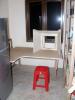
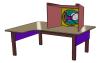
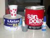
I decided it was time to make a spray booth. It is positioned under the window in the pantry, next to the beer cooler. The 8" diameter vent pipe will be hung out of the window. Hopefully the filter screen will stop enough overspray so I don’t get a colored streak down the side of the house. The table height is a mere 26” and is designed around the stool and a comfortable working height. No point painting the table, as it is going to get messed up anyway. Room for the drying wheel to the right. I already have a squirrel cage fan in the workshop and will be buying the same for the booth. It should be strong enough to suck the seeds from a pound of grapes. I can’t allow any paint debris in the house, as it is rented. For this reason, I will be using water based paints. Their will be a filter frame in front of the fan, but not built yet. I cannot find any purpose made filter sheets, so I will be using a thin stretchy material that I found. I can adjust its filter capabilities by stretching and/or layering. It was very cheap and sold by the kilogram, so I bought 5Kg, enough for a few spares. Still some work to do. Fit the fan and ducting, build the filter screen. Already have shelves to the right for supplies. Need to build airbrush holders, hairbrush holder, lure racks. Lighting and electrics need sorting out. I have a good design of an all in one hands free lure holder/mesh screen holder, in my head. If it works out, I will post this separately. The compressor will be in a sound proof box and will be located outside on a very small balcony, to the right of the window. Not ideal, but the table is too low to encompass the soundproof box unfortunately. I will probably have to make a junction block for the air to the brushes. So I thought I would throw it out to you guys for comments, before I get too far along, just incase I am missing something. Dave
-
DIY An Instant 1/2 Rd RTV Silicone Mold For Under A Buck.
Vodkaman replied to Husky's topic in Soft Plastics
Thanks Husky, I will give that a go. Dave -
DIY An Instant 1/2 Rd RTV Silicone Mold For Under A Buck.
Vodkaman replied to Husky's topic in Soft Plastics
I had one go at this idea, as I cannot get the plastics the soft plastics guys use in USA. I tried it in a PoP mold that I made very quickly. Maybe I did not seal it enough, but the silicone stuck so well to the surface of the mold, I could not remove it without destroying the mold. I intend comming back to this idea, as I think that this silicone material has potential as a bait. Next time I will experiment with release agents and obviously seal the PoP better. Thinned D2T might be a better option, I used Elmers last time. If you do try casting silicone, please post back what you try, success or failure, so we can learn. Thanks. Dave -
And proud of it Nil, proud of it. Thanks. Dave
-
If I was to tackle a project like this, I would start with a block of soft clay. Using clay carving tools, remove clay and set the master into the clay. No need for accuracy or setting as low as the parting line, just deep enough that the soft plastic master can be safely retrieved after curing. Build the box and pour the PoP. Remove the master and fully dry the PoP mold half. Using a belt sander, I would then sand down to what I want as a parting line. Using a drill and a burr, create location bumps, as the mold face is now very flat and will not locate by itself. Re-build the box, replace the master and pour the second half. The pour hole/funnel can either be molded with clay or cut after completion with a drill and burr. If I was making an RTV mold of the soft plastic master, I would still make the PoP mold as described above, as far as belt sanding and creating the locator bumps. I would also add a clay pour hole (half). Replace the master and pour the RTV. Once cured, remove plaster (store for future molds), invert and pour the second half of the RTV two piece. I have made RTV molds of crank bodies using a similar technique to this in the past. More steps involved, but it makes for a very neat mold and a casting with a neat and minimal parting line. Dave ps, for injection, I would drill the pour hole after molding, starting small and increasing the drill size gradually. As the drill diameter gets larger, it may be better to turn the drill by hand, as the plaster cuts very easy. Would not want to destroy the mold at the last stage.
-
The pics will be comming back one way or another, even if I have to shoot them again. What did you think of the jig? It has been working well so far. Dave
-
I have a slight problem, I have managed to delete every pic I ever posted. Jerry is working on it, but it looks like I am going to have to re-upload all the pics, could take months! Here's the discussion: http://www.tackleund...650#entry152650 Here are the pics for now. Dave
-
Nice pours, nothing wrong with those. Thanks for posting. Maybe more people might give it a try after seeing the quality that is attainable. Dave


